


The way each instruction is described Example
3-37 Instruction SetSPRU733
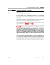
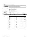
Compatibility The C62x, C64x, and C67x DSPs share an instruction set. All of the
instructions valid for the C62x DSP are also valid for the C67x DSP. This
section identifies which DSP family the instruction is valid.
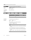
Description Instruction execution and its effect on the rest of the processor or memory
contents are described. Any constraints on the operands imposed by the
processor or the assembler are discussed. The description parallels and
supplements the information given by the execution block.
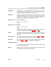
Execution for .L1, .L2 and .S1, .S2 Opcodes
if (cond) src1 + src2
→ dst
else nop
Execution for .D1, .D2 Opcodes
if (cond) src2 + src1
→ dst
else nop
The execution describes the processing that takes place when the instruction
is executed. The symbols are defined in Table 3−1 (page 3-2).
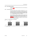
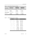
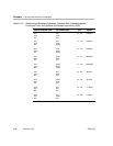
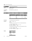
Pipeline This section contains a table that shows the sources read from, the destina-
tions written to, and the functional unit used during each execution cycle of the
instruction.
Instruction Type This section gives the type of instruction. See section 4.2 (page 4-12) for
information about the pipeline execution of this type of instruction.
Delay Slots This section gives the number of delay slots the instruction takes to execute
See section 3.4 (page 3-14) for an explanation of delay slots.
Functional Unit Latency
This section gives the number of cycles that the functional unit is in use during
the execution of the instruction.
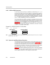
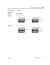
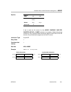
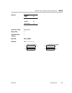
Example Examples of instruction execution. If applicable, register and memory values
are given before and after instruction execution.