


Parallel Operations
Instruction Set3-16 SPRU733
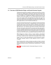
3.5 Parallel Operations
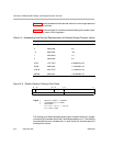
Instructions are always fetched eight at a time. This constitutes a fetch packet.
The basic format of a fetch packet is shown in Figure 3−3. Fetch packets are
aligned on 256-bit (8-word) boundaries.
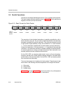
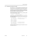
Figure 3−3. Basic Format of a Fetch Packet
pppppppp
Instruction
A
00000b
Instruction
B
00100b
Instruction
C
01000b
Instruction
D
01100b
Instruction
E
10000b
Instruction
F
10100b
Instruction
G
11000b
Instruction
H
11100b
LSBs of
the byte
address
31 0 31 0 31 0 31 0 31 0 31 0 31 0 31 0
The execution of the individual instructions is partially controlled by a bit in
each instruction, the p-bit. The p-bit (bit 0) determines whether the instruction
executes in parallel with another instruction. The p-bits are scanned from left
to right (lower to higher address). If the p-bit of instruction i is 1, then instruction
i + 1 is to be executed in parallel with (in the the same cycle as) instruction i.
If the p-bit of instruction i is 0, then instruction i + 1 is executed in the cycle after
instruction i. All instructions executing in parallel constitute an execute packet.
An execute packet can contain up to eight instructions. Each instruction in an
execute packet must use a different functional unit.
On the C67x DSP, an execute packet cannot cross an 8-word boundary;
therefore, the last p-bit in a fetch packet is always cleared to 0, and each fetch
packet starts a new execute packet. On the C67x+ DSP, an execute packet
can cross an 8-word boundary.
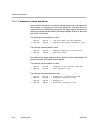
There are three types of p-bit patterns for fetch packets. These three p-bit pat-
terns result in the following execution sequences for the eight instructions:
Fully serial
Fully parallel
Partially serial
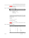
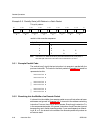
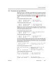
Example 3−1 through Example 3−3 show the conversion of a p-bit sequence
into a cycle-by-cycle execution stream of instructions.