


Opcode Map Symbols and Meanings
C-3.D Unit Instructions and Opcode MapsSPRU733
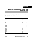
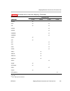
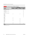
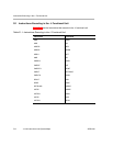
C.2 Opcode Map Symbols and Meanings
Table C−2 lists the symbols and meanings used in the opcode maps.
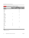
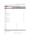
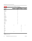
Table C−2. .D Unit Opcode Map Symbol Definitions
Symbol Meaning
baseR base address register
creg 3-bit field specifying a conditional register
dst destination. For compact instructions, dst is coded as an offset from either A16 or B16
depending on the value of the t bit.
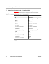
mode addressing mode, see Table C−3
offsetR register offset
op opfield; field within opcode that specifies a unique instruction
p parallel execution; 0 = next instruction is not executed in parallel, 1 = next instruction is
executed in parallel
r LDDW instruction
s side A or B for destination; 0 = side A, 1 = side B. For compact instructions, side of base ad-
dress (ptr) register; 0 = side A, 1 = side B.
src source. For compact instructions, src is coded as an offset from either A16 or B16 depending
on the value of the t bit.
src1 source 1
src2 source 2
x cross path for src2; 0 = do not use cross path, 1 = use cross path
y .D1 or .D2 unit; 0 = .D1 unit, 1 = .D2 unit
z
test for equality with zero or nonzero