


Individual Interrupt Control
5-15InterruptsSPRU733
5.3.4 Returning From Interrupt Servicing
After RESET goes high, the control registers are brought to a known value and
program execution begins at address 0h. After nonmaskable and maskable
interrupt servicing, use a branch to the corresponding return pointer register
to continue the previous program execution.
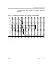
5.3.4.1 CPU State After RESET
After RESET, the control registers and bits contain the following values:
AMR, ISR, ICR, IFR, and ISTP = 0
IER = 1h
IRP and NRP = undefined
CSR bits 15−0 = 100h in little-endian mode
= 000h in big-endian mode
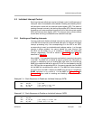
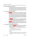
5.3.4.2 Returning From Nonmaskable Interrupts
The NMI return pointer register (NRP), shown in Figure 2−12 (page 2-22),
contains the return pointer that directs the CPU to the proper location to contin-
ue program execution after NMI processing. A branch using the address in
NRP (B NRP) in your interrupt service routine returns to the program flow
when NMI servicing is complete. Example 5−8 shows how to return from an
NMI.
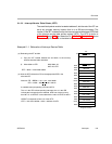
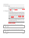
Example 5−8. Code to Return From NMI
B NRP ; return, sets NMIE
NOP 5 ; delay slots
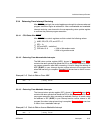
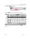
5.3.4.3 Returning From Maskable Interrupts
The interrupt return pointer register (IRP), shown in Figure 2−9 (page 2-19),
contains the return pointer that directs the CPU to the proper location to contin-
ue program execution after processing a maskable interrupt. A branch using
the address in IRP (B IRP) in your interrupt service routine returns to the
program flow when interrupt servicing is complete. Example 5−9 shows how
to return from a maskable interrupt.
Example 5−9. Code to Return from a Maskable Interrupt
B IRP ; return, moves PGIE to GIE
NOP 5 ; delay slots