


Interrupt Detection and Processing
5-19InterruptsSPRU733
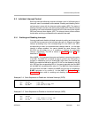
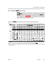
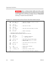
5.4.4 Setting the RESET Interrupt Flag
RESET must be held low for a minimum of 10 clock cycles. Four clock cycles
after RESET goes high, processing of the reset vector begins. The flag for
RESET
(IF0) in the IFR is set by the low-to-high transition of the RESET signal
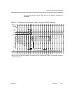
on the CPU boundary. In Figure 5−5, IF0 is set during CPU cycle 15. This tran-
sition is detected on a clock-cycle by clock-cycle basis and is not affected by
memory stalls that might extend a CPU cycle.
Figure 5−5. RESET Interrupt Detection and Processing: Pipeline Operation
Reset ISFP
n+7
n+6
Pipeline flush
E1DCDPPRPWPSPG
PG
PS
PW
PR
DP
DC
E1
n+5
n+4
n+3
n+2
n+1
n
Execute
packet
INUM
IACK
IF0
RESET
Clock cycle
0000000000000000
1716151413
12
11109876543
2
10
Cycles 15−21:
Nonreset interrupt
processing is disabled
1716151413
12
11109876543
2
10
CPU cycle
at pin
0
PG
PS
PW
PR
DP
DC
E2E1
00000
2221201918
0
2221201918
†
IF0 is set on the next CPU cycle boundary after a 4-clock cycle delay after the rising edge of RESET.
‡
After this point, interrupts are still disabled. All nonreset interrupts are disabled when NMIE = 0. All maskable interrupts are
disabled when GIE = 0.