


Pipeline Operation Overview
Pipeline4-2 SPRU733
4.1 Pipeline Operation Overview
The pipeline phases are divided into three stages:
Fetch
Decode
Execute
All instructions in the C67x DSP instruction set flow through the fetch, decode,
and execute stages of the pipeline. The fetch stage of the pipeline has four
phases for all instructions, and the decode stage has two phases for all instruc-
tions. The execute stage of the pipeline requires a varying number of phases,
depending on the type of instruction. The stages of the C67x DSP pipeline are
shown in Figure 4−1.
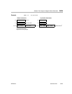
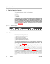
Figure 4−1. Pipeline Stages
Fetch Execute
Decode
4.1.1 Fetch
The fetch phases of the pipeline are:
PG: Program address generate
PS: Program address send
PW: Program access ready wait
PR: Program fetch packet receive
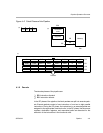
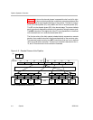
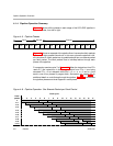
The C67x DSP uses a fetch packet (FP) of eight instructions. All eight of the
instructions proceed through fetch processing together, through the PG, PS,
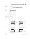
PW, and PR phases. Figure 4−2(a) shows the fetch phases in sequential order
from left to right. Figure 4−2(b) is a functional diagram of the flow of instructions
through the fetch phases. During the PG phase, the program address is gener-
ated in the CPU. In the PS phase, the program address is sent to memory. In
the PW phase, a memory read occurs. Finally, in the PR phase, the fetch pack-
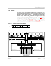
et is received at the CPU. Figure 4−2(c) shows fetch packets flowing through
the phases of the fetch stage of the pipeline. In Figure 4−2(c), the first fetch
packet (in PR) is made up of four execute packets, and the second and third
fetch packets (in PW and PS) contain two execute packets each. The last fetch
packet (in PG) contains a single execute packet of eight single-cycle instruc-
tions.