


Control Register File
2-13CPU Data Paths and ControlSPRU733
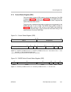
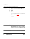
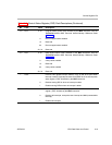
2.7.4 Control Status Register (CSR)
The control status register (CSR) contains control and status bits. The CSR
is shown in Figure 2−4 and described in Table 2−7. For the PWRD, EN, PCC,
and DCC fields, see the device-specific data manual to see if it supports the
options that these fields control.
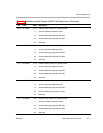
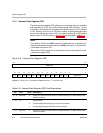
The power-down modes and their wake-up methods are programmed by the
PWRD field (bits 15−10) of CSR. The PWRD field of CSR is shown in
Figure 2−5. When writing to CSR, all bits of the PWRD field should be
configured at the same time. A logic 0 should be used when writing to the
reserved bit (bit 15) of the PWRD field.
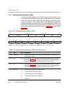
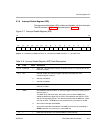
Figure 2−4. Control Status Register (CSR)
31 24 23 16
CPU ID
REVISION ID
R-0 R-x
†
15 10 9 8 7 5 4 2 1 0
PWRD
SAT EN PCC DCC PGIE GIE
R/W-0 R/WC-0 R-x R/W-0 R/W-0 R/W-0 R/W-0
Legend: R = Readable by the MVC instruction; W = Writeable by the MVC instruction; WC = Bit is cleared on write; -n = value
after reset; -x = value is indeterminate after reset
†
See the device-specific data manual for the default value of this field.
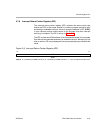
Figure 2−5. PWRD Field of Control Status Register (CSR)
15 14 13 12 11 10
Reserved
Enabled or nonenabled interrupt wake Enabled interrupt wake PD3 PD2 PD1
R/W-0 R/W-0 R/W-0 R/W-0 R/W-0 R/W-0
Legend: R = Readable by the MVC instruction; W = Writeable by the MVC instruction; -n = value after reset