


Control Register File
2-21CPU Data Paths and ControlSPRU733
2.7.10 Interrupt Service Table Pointer Register (ISTP)
The interrupt service table pointer register (ISTP) is used to locate the interrupt
service routine (ISR). The ISTB field identifies the base portion of the address
of the interrupt service table (IST) and the HPEINT field identifies the specific
interrupt and locates the specific fetch packet within the IST. The ISTP is
shown in Figure 2−11 and described in Table 2−12. See section 5.1.2.2 on
page 5-9 for a discussion of the use of the ISTP.
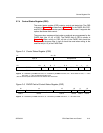
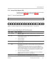
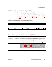
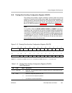
Figure 2−11.Interrupt Service Table Pointer Register (ISTP)
31 16
ISTB
R/W-0
15 109 543210
ISTB
HPEINT 0 0 0 0 0
R/W-0 R-0 R-0
Legend: R = Readable by the MVC instruction; W = Writeable by the MVC instruction; -n = value after reset
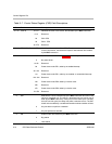
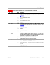
Table 2−12. Interrupt Service Table Pointer Register (ISTP) Field Descriptions
Bit Field Value Description
31−10 ISTB 0−3F FFFFh Interrupt service table base portion of the IST address. This field is cleared
to 0 on reset; therefore, upon startup the IST must reside at address 0. After
reset, you can relocate the IST by writing a new value to ISTB. If relocated,
the first ISFP (corresponding to RESET
) is never executed via interrupt
processing, because reset clears the ISTB to 0. See Example 5−1.
9−5 HPEINT 0−1Fh Highest priority enabled interrupt that is currently pending. This field indicates
the number (related bit position in the IFR) of the highest priority interrupt (as
defined in Table 5−1 on page 5-3) that is enabled by its bit in the IER. Thus,
the ISTP can be used for manual branches to the highest priority enabled in-
terrupt. If no interrupt is pending and enabled, HPEINT contains the value 0.
The corresponding interrupt need not be enabled by NMIE (unless it is NMI)
or by GIE.
4−0 − 0 Cleared to 0 (fetch packets must be aligned on 8-word (32-byte) boundaries).