


Control Register File
CPU Data Paths and Control2-8 SPRU733
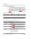
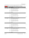
2.7.1 Register Addresses for Accessing the Control Registers
Table 2−4 lists the register addresses for accessing the control register file.
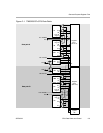
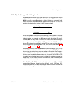
One unit (.S2) can read from and write to the control register file. Each control
register is accessed by the MVC instruction. See the MVC instruction descrip-
tion, page 3-180, for information on how to use this instruction.
Additionally, some of the control register bits are specially accessed in other
ways. For example, arrival of a maskable interrupt on an external interrupt pin,
INTm, triggers the setting of flag bit IFRm. Subsequently, when that interrupt
is processed, this triggers the clearing of IFRm and the clearing of the global
interrupt enable bit, GIE. Finally, when that interrupt processing is complete,
the B IRP instruction in the interrupt service routine restores the pre-interrupt
value of the GIE. Similarly, saturating instructions like SADD set the SAT
(saturation) bit in the control status register (CSR).
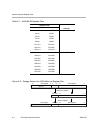
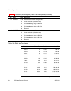
Table 2−4. Register Addresses for Accessing the Control Registers
Acronym Register Name Address Read/ Write
AMR Addressing mode register 00000 R, W
CSR Control status register 00001 R, W
FADCR Floating-point adder configuration 10010 R, W
FAUCR Floating-point auxiliary configuration 10011 R, W
FMCR Floating-point multiplier configuration 10100 R, W
ICR Interrupt clear register 00011 W
IER Interrupt enable register 00100 R, W
IFR Interrupt flag register 00010 R
IRP Interrupt return pointer 00110 R, W
ISR Interrupt set register 00010 W
ISTP Interrupt service table pointer 00101 R, W
NRP Nonmaskable interrupt return pointer 00111 R, W
PCE1
Program counter, E1 phase 10000 R
Legend: R = Readable by the MVC instruction; W = Writeable by the MVC instruction