


Control Register File
CPU Data Paths and Control2-16 SPRU733
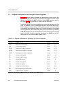
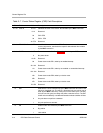
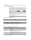
2.7.5 Interrupt Clear Register (ICR)
The interrupt clear register (ICR) allows you to manually clear the maskable
interrupts (INT15−INT4) in the interrupt flag register (IFR). Writing a 1 to any
of the bits in ICR causes the corresponding interrupt flag (IFn) to be cleared
in IFR. Writing a 0 to any bit in ICR has no effect. Incoming interrupts have
priority and override any write to ICR. You cannot set any bit in ICR to affect
NMI or reset. The ISR is shown in Figure 2−6 and described in Table 2−8.
Note:
Any write to ICR (by the MVC instruction) effectively has one delay slot
because the results cannot be read (by the MVC instruction) in IFR until two
cycles after the write to ICR.
Any write to ICR is ignored by a simultaneous write to the same bit in the
interrupt set register (ISR).
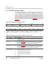
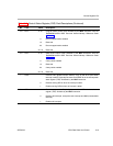
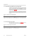
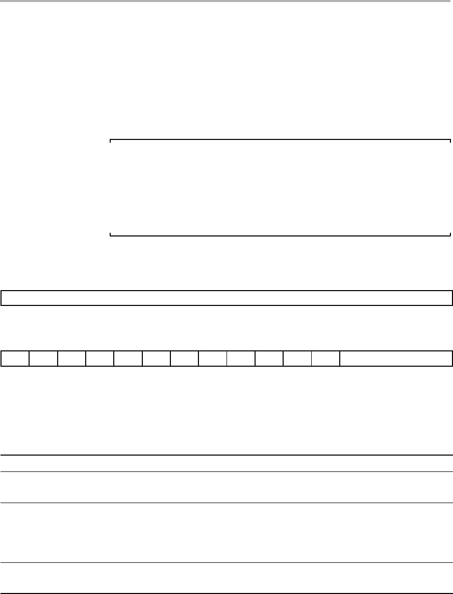
Figure 2−6. Interrupt Clear Register (ICR)
31 16
Reserved
R-0
1514131211109876543 0
IC15 IC14 IC13 IC12 IC11 IC10 IC9 IC8 IC7 IC6 IC5 IC4 Reserved
W-0 R-0
Legend: R = Read only; W = Writeable by the MVC instruction; -n = value after reset
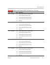
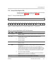
Table 2−8. Interrupt Clear Register (ICR) Field Descriptions
Bit Field Value Description
31−16 Reserved 0 Reserved. The reserved bit location is always read as 0. A value written to this
field has no effect.
15−4 ICn Interrupt clear.
0 Corresponding interrupt flag (IFn) in IFR is not cleared.
1 Corresponding interrupt flag (IFn) in IFR is cleared.
3−0
Reserved 0 Reserved. The reserved bit location is always read as 0. A value written to this
field has no effect.