


Delay Slots
Instruction Set3-14 SPRU733
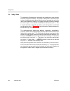
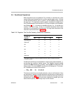
3.4 Delay Slots
The execution of floating-point instructions can be defined in terms of delay
slots and functional unit latency. The number of delay slots is equivalent to the
number of additional cycles required after the source operands are read for the
result to be available for reading. For a single-cycle type instruction, operands
are read on cycle i and produce a result that can be read on cycle i + 1. For
a 4-cycle instruction, operands are read on cycle i and produce a result that
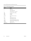
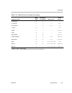
can be read on cycle i + 4. Table 3−8 shows the number of delay slots associat-
ed with each type of instruction.
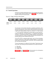
The double-precision floating-point addition, subtraction, multiplication,
compare, and the 32-bit integer multiply instructions also have a functional unit
latency that is greater than 1. The functional unit latency is equivalent to the
number of cycles that the instruction uses the functional unit read ports. For
example, the ADDDP instruction has a functional unit latency of 2. Operands
are read on cycle i and cycle i + 1. Therefore, a new instruction cannot begin
until cycle i + 2, rather than i + 1. ADDDP produces a result that can be read
on cycle i + 7, because it has six delay slots.
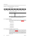
Delay slots are equivalent to an execution or result latency. All of the instruc-
tions in the C67x DSP have a functional unit latency of 1. This means that a
new instruction can be started on the functional unit each cycle. Single-cycle
throughput is another term for single-cycle functional unit latency.