


TMS320C67x DSP Architecture
Introduction1-8 SPRU733
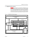
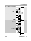
1.4.1 Central Processing Unit (CPU)
The C67x CPU, in Figure 1−1, is common to all the C62x/C64x/C67x devices.
The CPU contains:
Program fetch unit
Instruction dispatch unit
Instruction decode unit
Two data paths, each with four functional units
32 32-bit registers
Control registers
Control logic
Test, emulation, and interrupt logic
The program fetch, instruction dispatch, and instruction decode units can
deliver up to eight 32-bit instructions to the functional units every CPU clock
cycle. The processing of instructions occurs in each of the two data paths (A
and B), each of which contains four functional units (.L, .S, .M, and .D) and 16
32-bit general-purpose registers. The data paths are described in more detail
in Chapter 2. A control register file provides the means to configure and control
various processor operations. To understand how instructions are fetched,
dispatched, decoded, and executed in the data path, see Chapter 4.
1.4.2 Internal Memory
The C67x DSP has a 32-bit, byte-addressable address space. Internal
(on-chip) memory is organized in separate data and program spaces. When
off-chip memory is used, these spaces are unified on most devices to a single
memory space via the external memory interface (EMIF).
The C67x DSP has two 32-bit internal ports to access internal data memory.
The C67x DSP has a single internal port to access internal program memory,
with an instruction-fetch width of 256 bits.
1.4.3 Memory and Peripheral Options
A variety of memory and peripheral options are available for the C6000
platform:
Large on-chip RAM, up to 7M bits
Program cache
2-level caches
32-bit external memory interface supports SDRAM, SBSRAM, SRAM,
and other asynchronous memories for a broad range of external memory
requirements and maximum system performance.