


Control Register File
2-17CPU Data Paths and ControlSPRU733
2.7.6 Interrupt Enable Register (IER)
The interrupt enable register (IER) enables and disables individual interrupts.
The IER is shown in Figure 2−7 and described in Table 2−9.
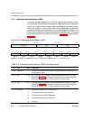
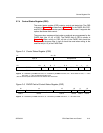
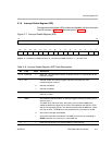
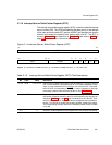
Figure 2−7. Interrupt Enable Register (IER)
31 16
Reserved
R-0
15141312111098765432 10
IE15 IE14 IE13 IE12 IE11 IE10 IE9 IE8 IE7 IE6 IE5 IE4 Reserved NMIE 1
R/W-0 R-0 R/W-0 R-1
Legend: R = Readable by the MVC instruction; W = Writeable by the MVC instruction; -n = value after reset
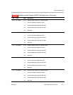
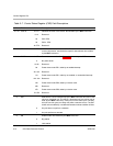
Table 2−9. Interrupt Enable Register (IER) Field Descriptions
Bit Field Value Description
31−16 Reserved 0 Reserved. The reserved bit location is always read as 0. A value written to this
field has no effect.
15−4 IEn Interrupt enable. An interrupt triggers interrupt processing only if the
corresponding bit is set to 1.
0 Interrupt is disabled.
1 Interrupt is enabled.
3−2
Reserved 0 Reserved. The reserved bit location is always read as 0. A value written to this
field has no effect.
1 NMIE Nonmaskable interrupt enable. An interrupt triggers interrupt processing only if
the bit is set to 1.
The NMIE bit is cleared at reset. After reset, you must set the NMIE bit to
enable the NMI and to allow INT15−INT4 to be enabled by the GIE bit in CSR
and the corresponding IER bit. You cannot manually clear the NMIE bit; a write
of 0 has no effect. The NMIE bit is also cleared by the occurrence of an NMI.
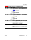
0 All nonreset interrupts are disabled.
1 All nonreset interrupts are enabled. The NMIE bit is set only by completing a
B NRP instruction or by a write of 1 to the NMIE bit.
0 1 1 Reset interrupt enable. You cannot disable the reset interrupt.