


Data Address Paths
2-7CPU Data Paths and ControlSPRU733
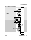
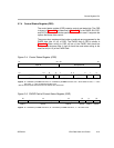
2.6 Data Address Paths
The data address paths (DA1 and DA2) are each connected to the .D units in
both data paths. This allows data addresses generated by any one path to
access data to or from any register.
The DA1 and DA2 resources and their associated data paths are specified as
T1 and T2, respectively. T1 consists of the DA1 address path and the LD1 and
ST1 data paths. For the C67x DSP, LD1 is comprised of LD1a and LD1b to
support 64-bit loads. Similarly, T2 consists of the DA2 address path and the
LD2 and ST2 data paths. For the C67x DSP, LD2 is comprised of LD2a and
LD2b to support 64-bit loads.
The T1 and T2 designations appear in the functional unit fields for load and
store instructions. For example, the following load instruction uses the .D1 unit
to generate the address but is using the LD2 path resource from DA2 to place
the data in the B register file. The use of the DA2 resource is indicated with the
T2 designation.
LDW .D1T2 *A0[3],B1
2.7 Control Register File
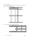
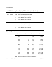
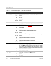
Table 2−3 lists the control registers contained in the control register file.
Table 2−3. Control Registers
Acronym Register Name Section
AMR Addressing mode register 2.7.3
CSR Control status register 2.7.4
ICR Interrupt clear register 2.7.5
IER Interrupt enable register 2.7.6
IFR Interrupt flag register 2.7.7
IRP Interrupt return pointer register 2.7.8
ISR Interrupt set register 2.7.9
ISTP Interrupt service table pointer register 2.7.10
NRP Nonmaskable interrupt return pointer register 2.7.11
PCE1
Program counter, E1 phase 2.7.12
Data Address Paths / Control Register File