


Control Register File
CPU Data Paths and Control2-10 SPRU733
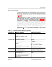
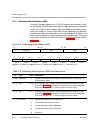
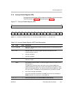
2.7.3 Addressing Mode Register (AMR)
For each of the eight registers (A4–A7, B4–B7) that can perform linear or circu-
lar addressing, the addressing mode register (AMR) specifies the addressing
mode. A 2-bit field for each register selects the address modification mode:
linear (the default) or circular mode. With circular addressing, the field also
specifies which BK (block size) field to use for a circular buffer. In addition, the
buffer must be aligned on a byte boundary equal to the block size. The mode
select fields and block size fields are shown in Figure 2−3 and described in
Table 2−5.
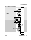
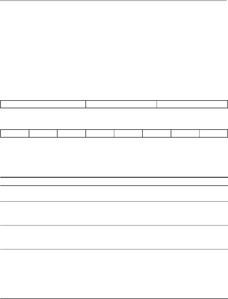
Figure 2−3. Addressing Mode Register (AMR)
31 26 25 21 20 16
Reserved
BK1 BK0
R-0 R/W-0 R/W-0
15 14 13 12 11 10 9 8 7 6 5 4 3 2 1 0
B7 MODE
B6 MODE B5 MODE B4 MODE A7 MODE A6 MODE A5 MODE A4 MODE
R/W-0 R/W-0 R/W-0 R/W-0 R/W-0 R/W-0 R/W-0 R/W-0
Legend: R = Readable by the MVC instruction; W = Writeable by the MVC instruction; -n = value after reset
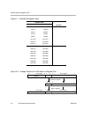
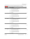
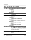
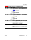
Table 2−5. Addressing Mode Register (AMR) Field Descriptions
Bit Field Value Description
31−26 Reserved 0 Reserved. The reserved bit location is always read as 0. A value written to
this field has no effect.
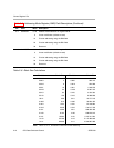
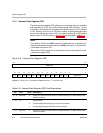
25−21 BK1 0−1Fh Block size field 1. A 5-bit value used in calculating block sizes for circular
addressing. Table 2−6 shows block size calculations for all 32 possibilities.
Block size (in bytes) = 2
(N+1)
, where N is the 5-bit value in BK1
20−16 BK0 0−1Fh Block size field 0. A 5-bit value used in calculating block sizes for circular
addressing. Table 2−6 shows block size calculations for all 32 possibilities.
Block size (in bytes) = 2
(N+1)
, where N is the 5-bit value in BK0
15−14 B7 MODE 0−3h Address mode selection for register file B7.
0 Linear modification (default at reset)
1h Circular addressing using the BK0 field
2h Circular addressing using the BK1 field
3h Reserved