


Overview
5-9InterruptsSPRU733
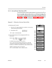
5.1.2.2 Interrupt Service Table Pointer (ISTP)
The reset fetch packet must be located at address 0, but the rest of the IST can
be at any program memory location that is on a 256-word boundary. The
location of the IST is determined by the interrupt service table base (ISTB) field
of the interrupt service table pointer register (ISTP). The ISTP is shown in
Figure 2−11 (page 2-21) and described in Table 2−12. Example 5−1 shows
the relationship of the ISTB to the table location.
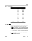
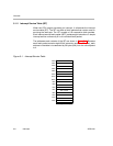
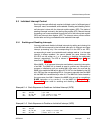
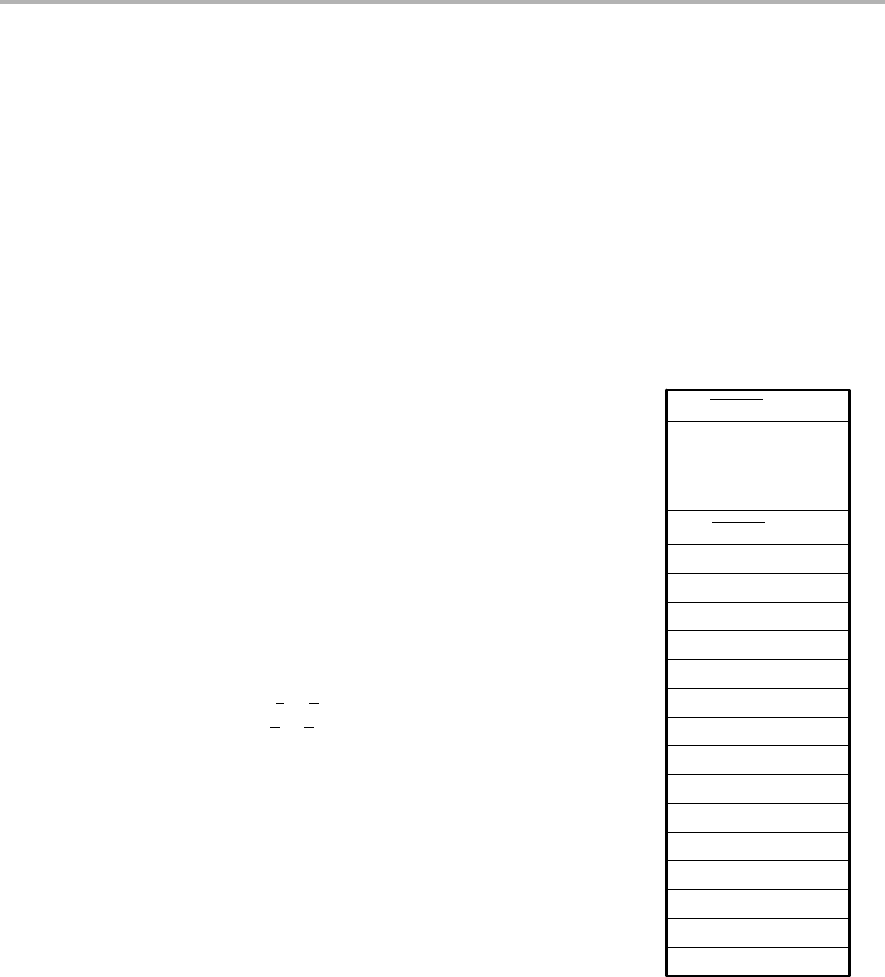
Example 5−1. Relocation of Interrupt Service Table
IST
NMI ISFP
Reserved
Reserved
INT4 ISFP
INT5 ISFP
INT6 ISFP
INT7 ISFP
INT8 ISFP
INT9 ISFP
INT10 ISFP
INT11 ISFP
INT12 ISFP
INT13 ISFP
INT14 ISFP
INT15 ISFP
0
820h
840h
860h
880h
8A0h
8C0h
8E0h
900h
920h
940h
96h0
980h
9A0h
9C0h
9E0h
Program memory
800h
RESET ISFP
1) Copy the IST, located between 0h and 200h, to the memory
location between 800h and A00h.
2) Write 800h to ISTP: MVK 800h, A2
MVC A2, ISTP
ISTP = 800h = 1000 0000 0000b
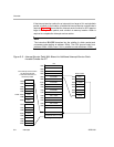
RESET ISFP
Assume: IFR = BBC0h = 1011 1011 1100 0000b
IER = 1230h = 0001
0010 0011 0001b
2 enabled interrupts pending: INT9 and INT12
The 1s in the IFR indicate pending interrupts; the 1s in the IER
indicate the interrupts that are enabled. INT9 has a higher priority
than INT12, so HPEINT is encoded with the value for INT9, 01001b.
HPEINT corresponds to bits 9−5 of the ISTP:
ISTP = 1001 0010 0000b = 920h = address of INT9
(b) How the ISTP directs the CPU to the appropriate ISFP in the
relocated IST
(a) Relocating the IST to 800h